|
Related Websites
|
CAPMAP
CBI, Cosmic Background Imager
DASI, Degree Angular Scale Interferometer
WMAP, Wilkinson Microwave Anisotropy Probe
|
|
|
|
|
|
| |
Observing the polarized CMB demands exquisite sensitivity and freedom from systematic errors. QUIET is an integrated approach to characterizing the CMB polarization power spectra using very large 20% band-width arrays of 40 GHz and 90 GHz polarimeters capable of meeting these requirements. The QUIET arrays offer the most sensitive detector technology for ground-based CMB observations at 100 GHz or below, and build on established techniques for controlling polarization systematic errors. We describe our methods for realizing each N-element dual-Stokes* array as a self-contained unit incorporating feed optics, polarizing elements, lock-in modulation, tunable detector biasing, and analog to digital conversion.
We present a phased approach for meeting our objectives both to take advantage of the readiness of the core QUIET technology for early return of science data, and to test strategies for reaching the new level of systematic control required by the high sensitivity of the QUIET detector arrays. In Phase I of the project, after operating a seven-element demonstration array at 90 GHz, we will build a 91-element array at 90 GHz and a 19-element array at 40 GHz. Each of these arrays, which have comparable sensitivity, will operate for one year on a 1m sid-fed Cassegrain telescope mounted on the Cosmic Background Imager (CBI) platform in Chajnantor, Chile, at an altitude of 5080 m.
In Phase II of the QUIET project, we will build four additional arrays: two 91-element 40 GHz arrays and two 397-element 90 GHz arrays. These large arrays will observe alternately on a set of three 2m telescopes mounted on the CBI platform and on the co-located Crawford Hill 7m telescope. The total QUIET project will have about 1000 polarimeters, each of which is expected to have equal or better sensitivity than a co-located ground-based polarization sensitive bolometer (PSB) detector.
Here, we give an overview of the QUIET detector arrays, and then provide details and status on the QUIET polarimeters, the feed horns and OMTs, the array electronics, the cryostat, and the optimizer apparatus. We conclude with discussion of the optics for QUIET.
*Each of the N elements simultaneously measures both Q and U, the linear Stokes parameters.
|
| |
|
|
| |
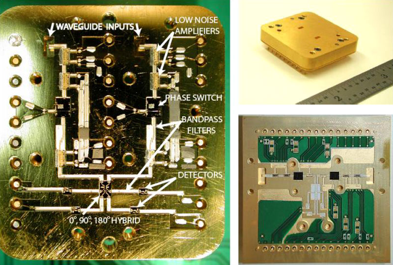
The key to the large focal plane arrays is the successful miniaturization of the correlation polarimeter into a postage stamp-sized module. QUIET relies on the recent breakthrough in millimeter-wave circuit technology and packaging at JPL, which enables large arrays of radiometers or polarimeters for modest cost. Each array element is based on a QUIET module: a compact IC-style package with waveguide inputs which can be built and tested in quantity with fully automated techniques adapted from the semiconductor industry. The module is a pseudo-correlation receiver comprising low noise amplifiers*, phase shifters, detector diodes, and passive components described below and shown in Figure 1. The polarization properties of an electromagnetic signal are fully characterized by the four Stokes parameters. Stokes I is the total intensity, while Stokes V is predicted to be 0 for the CMB. The remaining Stokes parameters are Q and U. Both Q and U are measured simultaneously by a single QUIET module with the introduction of an appropriate optical element: a circularly polarized orthomode transducer (OMT). This dual measurement is a distinct advantage over the polarization sensitive bolometer (PSB) modules on Planck, which each measure a single Stokes parameter.
*The low noise amplifiers are InP monolithic microwave integrated circuit (MMIC) high electron mobility transistor (HEMT) amplifiers.
|
| |
 Figure 1: Left: Photograph of the first QUIET 90 GHz receiver module. All of the parts associated with one input are labeled. Upper Right: Photograph of body of an earlier prototype 90 GHz module. The modules are 1.25'' x 1.14''. Lower Right: Photograph of the interior of a (2'' x 2'') 40 GHz module.
|
| |
The arrays of QUIET modules are populated on sets of printed circuit boards, providing lowcost, simple integration as rendered in Figure 2. The modules operate at 20K, cooled with a commercial refrigerator. Additional room temperature circuit boards, most of which are in the cryostat, simultaneously provide bias to the individual chips and demodulate, multiplex, and digitize the output signals. A set of flex-circuit cables provides the thermal isolation from the 20K modules.
Since we now have the technology to produce large numbers of low cost, compact receivers, we have developed complementary means to reduce cost and integration time for other aspects of the arrays. We will construct the feed horn arrays in a block of stacked plates, while the OMTs will be built as split blocks. Bias and data acquisition electronics will be effected with many replicas of a basic functional unit. Bias optimization will be automated and performed simultaneously for an entire array. The combination of the QUIET modules and these other highly integrated components produces an array engine, that can be tested, optimized, and operated as a unit.
|
| |
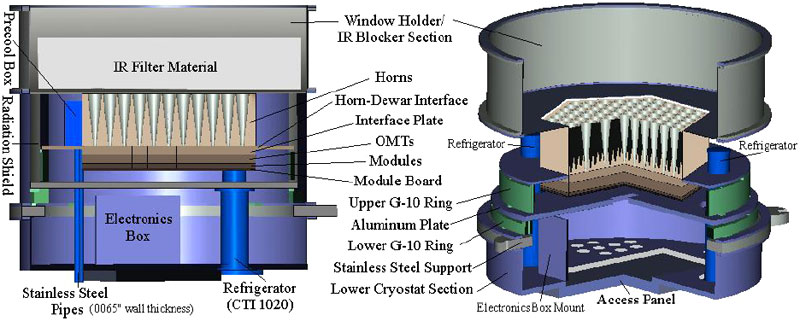
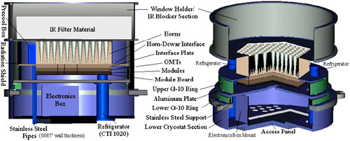 Figure 2: Schematic view of a QUIET cryostat shown with a 91 element array of W-band modules. Both G-10 rings make contact with the corresponding surfaces only through a fraction of their cross section in order to reduce thermal loading. Flexible printed circuit (not shown in the figure) connects the module board to the electronics back plane and the connectors in the bottom of the cryostat to the electronics box which resides in a 300 K cavity beneath the aluminum plate. The horns are held at ≈ 20 K and shielded from 300K radiation by a radiation shield (shown only in the figure on the left) held at ≈ 80 K on the top and sides and the aluminum plate (also 80K) on the bottom. The window holder section is separable from the rest of the cryostat and can be enlarged (wider at the top than the bottom, where it mates to the rest of the cryostat) or shrunk as necessary to provide the minimum required space for the window and IR-blocking material while keeping the cryostat edges out of the field of view of the horn array.
|
| |
|
|
| |
Correlation polarimeters measure polarized signals through either direct or indirect multiplication of the signals. This well-established technique offers the advantages of insensitivity to gain fluctuations and unpolarized signals, post-amplification gain modulation, and simultaneous detection of both Q and U Stokes parameters.
The inputs of the QUIET correlation receiver are two circularly polarized modes (L,R) = (Ex ± iEy)/(2)1/2, where Ex and Ey are the x and y components of the incident electric field (see Figure 3). The signals are amplified, one arm is phase switched with 0 or 180o, and combined with the other arm in a 180o hybrid coupler with outputs proportional to the sum and difference of the input wave-forms. These outputs are amplified versions of Ex and iEy, with the phase switch reversing their roles, and so the subsequent diode detectors (diodes 1 and 2 in Figure 3) detect Tx ∝ Ex2 or Ty ∝ Ey2. Modulation of the phase state results in Tx - Ty modulation on each diode. Gain fluctuations (1/f) due to the amplifiers are common-mode to both diodes and are strongly suppressed upon diode differencing. Phase modulation occurs at 4 kHz, faster than the 1/f knee of the atmosphere, amplifiers, and detectors. Similar receivers, using linear input polarizers, have been used for the PIQUE and CAPMAP experiments.
|
| |
 Figure 3: An overview of the polarimeter components on the integrated circuit module of QUIET. Left- and rightcircularly-polarized radiowaves enter from the top. Phase switches in each arm (indicated by ±1) are operated one at a time and provide the Dicke-switching which separates the polarized signal from the total power, as described in the text. The signals pass through low noise amplifiers (LNA) , and then enter a series of hybrid couplers, detailed in the text. PS indicates power splitters. The demodulated outputs of detector diodes 1 and 2 are proportional to the Stokes parameter Q while diodes 3 and 4 encode U after demodulation. Filters have been omitted for clarity.
|
| |
Simultaneous detection of the Stokes U is achieved through further processing. The Ex and iEy signals present at the output of the first coupler are combined in a 90o coupler, resulting in a voltage signal at the outputs given by Ex ± Ey depending upon the phase switch state and port position. Detecting these signals (at diodes 3 and 4 in Figure 3) yields measurements of (Tx + Ty)/2 ± ExEy, demodulation of which results in ExEy, the Stokes U parameter or the ± 45o polarized component of the incoming wave. This additional processing can be performed without loss of sensitivity, as it occurs after initial amplification of the signal.
|
| |
QUIET Polarimeter Sensitivity. For a total power radiometer, the minimum detectable signal is given by ΔTmin = Tsys/(βτ)1/2 , where Tsys is the system noise temperature, β is the RF bandwidth and τ is the integration time. The ΔTmin for a pseudo-correlation polarimeter measuring Tx - Ty is (21/2) higher, but with the (now standard) definition Q ≡ (Tx - Ty)/2, we find the minimum detectable Q is ΔQmin = Tsys/(2βτ)1/2, and similarly for ΔUmin. Moreover, one can show that the noise in U is uncorrelated with that in Q for an ideal polarimeter. Real systems are degraded by several percent, limited by the performance of components.
|
| |
QUIET Module Development Status. To meet the sensitivity goals, key functional requirements on the QUIET receiver modules include low noise, gain flatness, amplitude and phase balance in the two arms (for all states of the phase switches), and good isolation and balance in the hybrid couplers. Here we describe performance of the constituent devices (amplifiers, phase switches, passive components, detectors) and the module as a unit.
One key to mass production of the QUIET receivers is the repeatable performance achieved with MMIC integration of amplifiers and phase switches, with no mechanical tuning required. The QUIET modules use InP amplifiers, which achieve the lowest system temperatures available for these large bandwidths at frequencies below 100 GHz. We have demonstrated MMIC low noise amplifiers at 40 GHz (Q-band) and 90 GHz (W-band) with greater than 20% bandwidth and state-of-the-art noise performance. The 90-GHz four-stage amplifier used in QUIET was developed for radio astronomy applications and has been used in CAPMAP, SZA, SEQUOIA, AMiBA, JPL's Deep Space Network and at the Effelsberg Telescope. The typical noise measured for this design is between 40 and 50 K when cooled to 20 K as shown in Figure 4. At 40 GHz we have designed and proven a three-stage MMIC amplifier with 20 K typical noise. These amplifiers are currently being used in CAPMAP. The 180o phase switches have developed. Several designs covering 30-100 GHz were developed for the Planck Low Frequency Instrument which achieve 20% bandwidth with amplitude balance of 0.25 dB and phase error less than 10o. The switches are built using Northrop Grumman's InP PIN process and operate with less than 1 mW of power cryogenically.
|
| |
 Figure 4: Typical noise curves of one of our MMIC amplifiers. Two dozen of the 90 GHz amplifiers are currently
operating in CAPMAP with a typical receiver noise of 50 K. The 40 GHz amplifiers have 20 K typical noise and are
also operating in CAPMAP. We have demonstrated similar band-average performance in the QUIET modules.
Figure 4: Typical noise curves of one of our MMIC amplifiers. Two dozen of the 90 GHz amplifiers are currently
operating in CAPMAP with a typical receiver noise of 50 K. The 40 GHz amplifiers have 20 K typical noise and are
also operating in CAPMAP. We have demonstrated similar band-average performance in the QUIET modules.
|
| |
Several passive circuits are required to complete the polarimeter. These include input waveguide probes, 50Ω interconnecting lines and band-pass filters. These circuits are fabricated on low-cost alumina substrates. The 0o, 90o, 180o hybrids, which allow simultaneous detection of the Q and U Stokes parameters, are fabricated on either alumina or InP depending upon the tolerances required by the frequency of operation.
The detector diodes, which detect power by rectifying the RF signal, require DC biasing when cryogenically cooled. In our initial prototype modules we used commercially available GaAs Schottky diodes for the detectors. The hybrid circuitry around these diodes makes them more difficult to mass produce. We have opted to use HEMT gate diodes for detectors which also have good detection properties and have been measured to have acceptable 1/f and low video impedance when biased. The diodes we have developed for both radio frequencies allow for AC-coupling of the diodes at their inputs, and floating DC outputs, to ensure minimal ground-loops.
Our prototype receivers are shown in Figure 1. The Q- band receiver, with full Q/U capability was developed and tested in just the past seven months. The module has been tested in a cryostat with a magic-tee coupler at the input instead of an OMT. We measured a bandwidth of 5 GHz and a noise of 20K, nearly meeting all of the goals for the QUIET array. The isolation is a measure of the simultaneous gain and phase match of the two legs. We measured isolation of 12-20 dB. The gain and phases are matched using the bias voltages brought in through pins on the module. Limited gain slope tuning is possible with the drain voltages.
The W-band module is very similar to the Q-band module. We have demonstrated 50 K noise from the chains and isolation of 15 dB across a 12 GHz bandwidth. A second iteration addresses several problems found during the development of the prototype. This iteration improves the module stability, bandwidth, and manufacturability. Initial tests have shown excellent isolation and more than 15 GHz bandwidth.
|
| |
QUIET Module Mass Production. Mass production techniques are the key to building large arrays. The cellular phone and computer industries have developed high precision automated assembly techniques for assembly of semiconductor circuits. The second iteration QUIET modules were designed after consultation with two companies with experience in automated assembly of millimeter-wave parts. The tolerance afforded by these robotic techniques is 10 microns (3σ) which is more than adequate for our application. We have quotes from one of these companies and will soon issue a JPL-funded study contract to one or two vendors to develop an assembly process. We expect the assembly of the modules to cost an order of magnitude less than the manual assembly used for the prototypes.
We have funding from NASA to build the 91-element array at 90 GHz. This array will be built using the automated techniques described above.
|
| |
|
|
| |
The QUIET modules couple to the telescope optics through circularly-polarizing orthomode transducers (OMTs) and corrugated feed horns. We describe here our approach for achieving these components at low cost while meeting requirements for low systematic effects.
QUIET OMT Polarizers. The circularly polarizing OMTs split the incoming radiation into L and R. Good performance of the correlation polarimeter requires that the OMT polarizer have 20% bandwidth, low loss, good amplitude balance and flat phase response. Finally we require high isolation on the output ports to reduce sensitivity to the common mode total power signal.
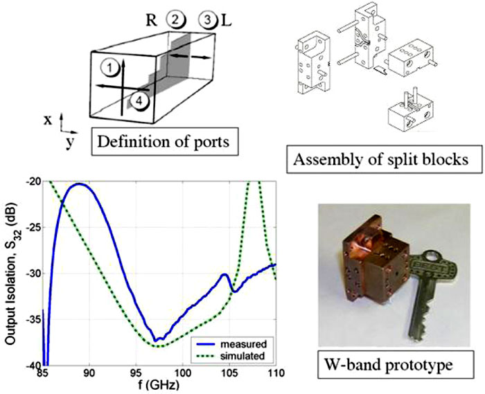
We have developed a W-band (84-104 GHz) design of a ridge waveguide septum polarizer, which we have manufactured and tested, and which meets our specifications. As a prototype, we have also built and tested a Ka-band (28-36 GHz) OMT polarizer based on the same design. The polarizer design is sketched in Figure 5 along with mechanical drawings, a photograph of a prototype, and data on the output isolation.
|
| |
 Figure 5: The OMT circular polarizer for QUIET. The top left figure gives the definition of the four ports for a ridge waveguide septum polarizer, while the top right figure shows the split block construction needed for realizing the septum polarizer, and the waveguide spreader which interfaces the polarizer to the QUIET module. A circularto- square step transition (not shown) will be machined into the OMT input. The lower left figure is a plot of the theoretical output-port isolation for the prototype design, with measured data overlaid. This parameter is important because it can give rise to I → Q coupling as described in the text. These data are limited by the measurement technique, but are already consistent with I → Q of a couple percent.
|
| |
QUIET Platelet Arrays. Conical, corrugated feed horns are the antenna of choice for studies of the CMB. They offer low insertion loss, very good return loss, excellent beam symmetry, very low side-lobe response, low cross-polarization, and they operate over a broad frequency band. The typical procedure for fabricating these horn antennas involves either direct machining on a CNC lathe or electroforming. Both of these techniques are too time consuming and too costly to consider for the QUIET arrays. A different approach is required.
With the realization that future space-borne mm-wave and submm-wave sensing satellites would require the sensitivity and resolution afforded by large focal plane arrays, researchers at Aerojet Corporation successfully fabricated and tested a 3x3 platelet horn array operating in the Wband. The platelet array technology uses a large number (typically 100) of thin sheets of metal each with a series of holes. The holes can be etched, laser cut, or direct machined, depending on the required thickness and tolerances. The corrugated pattern is generated by interspersing plates with larger and smaller holes. A precision fixture is used to align the plates so that the holes are concentric. The platelets are joined together using diffusion bonding or brazing techniques. Diffusion bonded platelets have been used in a wide range of applications ranging from platelet feed horn arrays to rocket engines. More recently, platelet arrays have been developed for higher frequency operations by QUIET collaborator Ed Wollack and others.
The groove pattern of the horns has been designed and modeled at JPL in coordination with the telescope design to minimize side-lobe and cross-polar response. The typical FWHM and gain of both the W and Q-band horns is 7.6o and 27.7 dB, respectively. The length of the W and Q-band platelet arrays is 13 cm and 28 cm respectively. The mass of a W and Q-band horn in the larger arrays is approximately 0.22 kg and 0.8 kg, respectively, including the interface plate needed to couple the horns to the OMTs. The interface plate incorporates a specially designed, low reflection, circular-to-circular transition to match the feed horn diameter to the OMT.
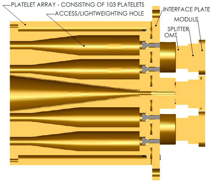
A seven-element W-band prototype array is currently being fabricated out of Al6061-T6 and will undergo characterization later this year (Figure 6). The primary components of the platelet array are 103 platelets each of which has a groove and a tooth, and a thick base plate for the diffusion bonding process. NASA funds provide the support for fabrication and testing of the Phase I 91- element W-band array and 19 element Q-band array. In order to maintain machining tolerances, the larger arrays for Phase II will typically consist of four subarrays comparable in size to the Phase I arrays. The testing consists of return loss measurements and near side-lobe measurements to check for fabrication and assembly defects. More extensive far side-lobe measurements will be performed after the tested polarimeters are delivered to Caltech/JPL and integrated onto the telescope.
|
| |
 Figure 6: A cutaway view of the prototype seven element W-band platelet array for QUIET. The platelet array consists of 103 equally thick platelets. Each platelet has a series of holes machined into it. Seven of the holes are counter-bored to form a tooth and a groove. Other holes are used as access/light-weighting holes. The interface plate resides between the platelet array and the OMTs and provides for, among other things, the mechanical connection to the cryostat. Also shown are the OMT, splitter and module blocks. The overall length and mass of the assembly is 17 cm and 2.7 kg, respectively.
|
| |
|
|
| |
Here we give an overview of the electronics needed for QUIET. The system will provide bias voltages and currents to the low noise amplifiers, provide a phase shifter signal at 4 kHz, provide current bias to the detector diodes, preamplification of the detector diode signals, and synchronous demodulation of the detector signals. In addition, the electronics will provide housekeeping functions allowing us to monitor detector DC voltages, HEMT drain currents, module operating temperatures, cryostat pressure, outside temperature, and other important items. The data acquisition system will sample the integrated as well as the demodulated detector signals (4 per module) at 100 Hz with 16 bit resolution. It also samples various housekeeping signals at a 1 Hz rate. |
| |
 Figure 7: The scheme for the implementation of the electronics is displayed. The blue area indicates the cryostat, the yellow area the VME crate, the green area the control hut.
|
| |
A sketch of the implementation is seen in Figure 7. The polarimeter modules will be mounted on so called Module Array Boards (MAB), providing protection circuitry and holding 7 modules each. Figure 8 shows the first W-band module plugged into its MAB. The 91 element array will consist of 13 of these MABs (some of different shape) to allow for a flexible assembly of the array. The electronics, located on cards in a separate cage in the lower part of the cryostat, will connect to the MABs via Flexible Printed Circuits (FPC) which provide thermal isolation and allow low-cost, easy integration. Cables connect the backplane of the dewar-internal cage to hermetic connectors on the bottom of the cryostat from where cables lead to an external VME-crate. The VME crate is the hub, where all information from the experiment (sky signals, housekeeping information, a GPS time stamp and the telescope encoder information) is collected. It also provides all clocks for use in the experiment (phase switching, multiplexing for housekeeping) and contains the interface for the main computer to control the DACs in the dewar for the various bias signals. |
| |
 Figure 8: The first W-band module is shown plugged into one Module Array Board (MAB), which can hold up to 7 modules and provides protection circuitry.
|
| |
For the digitization of the sky signals VME cards were designed which allow the simultaneous sampling of the signals at 800kHz with 18-bit resolution. One of the cards (partly stuffed) can be seen in Figure 9. All cards in the crate are synchronized with clock lines in the VME backplanes. An FPGA on each card allows for immediate flexible data processing and downsampling. For every 10ms the average and demodulated value of each signal line is computed, while the samples close to the transition edges of the 4kHz switching signal are ignored (which and how many samples is defined via a user-defined mask). The FPGA also allows easy implementation of various quadrature demodulation patterns if desired or the access to the raw 800kHz data, so that noise sources below 400kHz can be studied. |
| |
 Figure 9: One of the 6U VME cards for the DAQ, each of which contains 32 ADCs, is shown (partly stuffed).
|
| |
In addition to the data processing the FPGA program is used on one card (master card, defined with jumpers) to provide the necessary clock signals for the experiment derived from a 40MHz reference clock on that card.
The QUIET electronics plus the polarimeter modules form an array engine that can be tested, optimized, and operated as a unit.
|
| |
|
|
| |
Each QUIET cryostat must mechanically support, cryogenically cool, and optically mount an array. In addition, they will house the associated warm electronics, provide a large microwave transparenthigh vacuum window, and shield the horn array from infrared radiation.
Figure 2 shows a schematic of the primary elements of our cryostat design. We use a CTI Gifford-McMahon refrigerator to provide cooling (two cold heads for demonstration cryostats, four for production version). The array is mounted on a G-10 ring providing support and thermal isolation. The window will be made either of zotefoam or HDPE (both hold vacuum on an 18'' test setup and both have losses < 0.05% at 40 and 90 GHz for the thicknesses currently used). We are investigating ways to minimize window deflection in each case and candidate IR blocking materials to be located between the window and the horn array.
A single cryostat design will be employed for both W-band and Q-band cameras in each phase. The cryostat design for the 400 element arrays will follow the same general design but will be ≈ 1.6 times as large. Engineering work required to insure adequate support of the larger arrays and design of the correspondingly larger window will take place in the first year.
|
| |
|
|
| |
A key to the QUIET experiment is the replacement of painstakingly handcrafted polarimeters with mass-produced devices, allowing for much larger arrays of detectors. An efficient method is therefore needed to test and optimize them. The purpose of the QUIET Array Optimizer is to largely automate these processes. All optimization proceeds by varying the module bias parameters under computer control. Simultaneous control of the HEMT gates and drains, as well as phase switch diodes and detector diode bias (in total 18 parameters per module), provides the necessary degrees of freedom to tune the modules for noise, gain match, phase match and gain slopes.
The design of the optimizer can be seen in Figure 10. A box containing thermal and polarized sources is mounted on top of the dewar and can be rotated around the central axis. The box will hold two loads (liquid nitrogen, eccosorb), two metal reflector plates, a motor actuator and a sweeper. |
| |
 Figure 10. The picture shows the design of the optimizer, which can be mounted on top of the dewar and be rotated around a central axis.
|
| |
The loads are used for total power gain and noise measurements. The metal plates are used as polarized loads. The reflection on the plates leads to a calculable polarized signal, which changes with the box rotating. The insertion and extraction of the plates as well as the rotation is performed using motors under computer control. The sweeper is used for the determination of the phase match and bandwidth. A computer program will run the tuning and characterize all modules within 12 hours.
|
| |
|
|
| |
The pursuit of the faint B-mode polarization signals requires very careful instrument design. Extreme detector sensitivity is necessary, but not sufficient. The signal-to-noise regime in which we must work requires that special attention be paid to all potential sources of systematic errors, including those that commonly arise in the optical system. We have therefore focused a lot of attention into the design, optimization, and characterization of our optical system, including the development of a full physical optics model for arrays operating both on the large and small-scale platforms.
Sensitivity to gravity wave B-modes requires individual fields of view more than 10o across with many pixels, and observations of large sky areas. The optics must be small enough to accommodate a co-moving ground screen, minimizing the effects of horizon side-lobes. Similarly, sensitivity to gravitational lensing B-modes requires a beam size comparable to the angular scale of the peak of the lensing spectrum (~4') and very low noise at large l, which can be achieved over fairly small patches of sky.
We considered several options for satisfying these requirements. The two most promising were: a system with two 3-meter telescopes; and a system with three 2-m telescopes mounted on the CBI platform for large-scale observations, and the 7-m Crawford Hill telescope moved to the CBI site for small-scale observations. We chose the latter for several reasons: 1) it allows greater flexibility and larger l-space coverage; 2) the cost of building two 3-meter telescopes was considerably greater than the cost of using the CBI platform and the Crawford Hill telescope; and 3) while a 3-m telescope has a large focal surface, filling it with feeds would require either a gigantic single dewar or multiple dewars that would make inefficient use of focal surface real estate.
All designs that we considered used corrugated feed horns. Antenna-coupled feeds make more efficient use of focal plan area; however, the sacrifice in total sensitivity resulting from the lower packing efficiency of corrugated feeds is substantially more than compensated by their superior beam patterns and cross-polarization symmetry (- 40 dB over the required bandwidth of 80 - 105GHz at W-band and 38 - 46 GHz at Q-band).
Optical Design. To design each of the telescope systems, a geometric optics layout was generated and optimized for the largest possible field-of-view. This optimization also minimizes distortion, and hence cross-polarization. The beam patterns were then calculated numerically, using a Physical Optics (PO) program which determines the currents induced in the reflectors and propagates the fields to the sky.
Both designs use the same corrugated feed horns to couple radiation from the telescope to the detectors. To determine our feed horn aperture and spacing, we have maximized the aperture and minimized the spacing constrained by the requirement of hex-packing for our fixed module size at each frequency. The resulting outer feed diameter of 1.4'' yields a beam size of 7.6o at 90 GHz. The 40 GHz feed is a 9/4 scale of the 90GHz feed and so also has an 7.6o beam, but the feed diameter is 3''. Our design for the feed horns results in highly symmetric beam patterns for both polarizations, and low far side-lobes as one means of minimizing polarized ground pickup.
|
| |
2m Optics. The design goal for a system capable of probing the primordial B modes was to accommodate 800 W-band receivers, with a minimal number of cryostats in a flat focal plane, and producing beam sizes of less than 0.o5 with low instrumental and cross-polarizations, and low and controlled spill-overs. It was also desirable to fit the instruments on the CBI platform.
The 2m design we opted for accommodates 400 W-band receivers or 100 Q-band receivers, with each mirror machined as a single piece. Thus, we propose building three 2m systems, which will all be accommodated on the CBI platform as indicated in Figure 11. The design uses two reflectors of approximately equal size in a crossed arrangement, and is known as a side fed Cassegrain (or crossed Dragone system). The primary mirror is parabolic and the secondary is a concave hyperboloid. By correctly selecting the angle between the two reflectors, a system that has a wide field of view with minimal cross-polarization results.
|
| |
 Figure 11: Left: The side-fed Cassegrain arrangement of a parabolic primary with a (concave) hyperbolic secondary. This arrangement was selected for its excellent wide field performance and low cross-polarization. Right: Rendering of three of the 2m telescopes mounted on the CBI platform. In this configuration, radiation enters the system normal to the platform.
|
| |
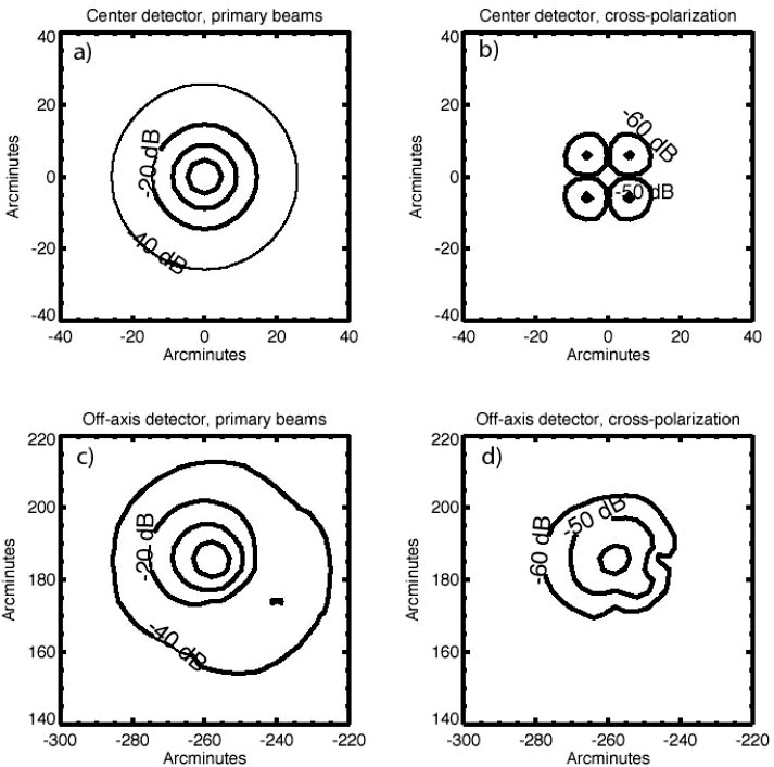
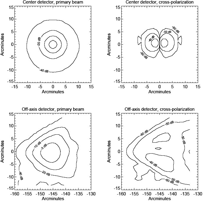
We calculated the optical properties of the system with a full PO program using the calculated corrugated field distribution to excite the optics. We calculated the 90GHz patterns for the central pixel as well as the extreme ± X and Y positions, and two of the 45o positions in the focal plane. In addition, for the central beam and one of the extreme positions, we calculated a full 4π sr response to be used in our analysis of systematics and ground screen requirements. For each beam simulated, we calculate X and Y co-polar and cross-polar responses. Two of these plots, showing co- and cross-polar responses for the central and one extreme (the "worst") feed are shown in Figure 12. A full-sky co-polar beam map for the extreme position is shown in Figure 13.
|
| |
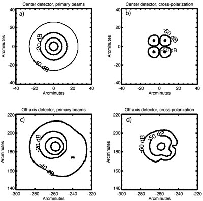 Figure 12: Large Scale Optics co- and cross- polarization. Physical optics simulation of the beam response for a) co-polar central feed; b) cross-polar central feed; c) co-polar for x = 9.8'', y = 7.2'' feed position on edge of array and; d) cross-polar for x = 9.8'', y = 7.2'' feed position. The contours in the co-polar plots are -3, -10, - 20 and -40 dBi. The contours for the cross-polar plots are -40, -50 and -60 dBi. For our science goals, -45 dBi in the cross-polar response is needed; this remarkable level of performance can only be achieved with corrugated feeds in the focal plane.
|
| |
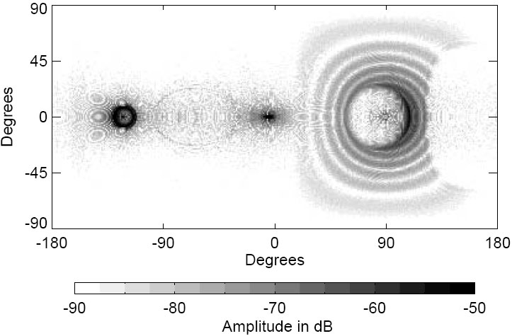
 Figure 13: 4π steradian plot of 1 m telescope beam response, calculated using PO methods, to determine the effects of spurious side-lobes which can lead to scan-synchronous signals. The grey-scale plot shows -50 dBi or larger lobes as black. The side-lobes are quite small, well behaved and constrained to a small solid angle and thus controllable with shielding. A calculation performed for the 2m telescopes confirms similarly good results even though below -60 dBi it required too much time to converge.
|
| |
The telescope design has excellent polarization properties with a large and flat field of view with an angular extent of 12o on the sky. At W-band the beam size is 0.o15 and at Q-band the beam size is 0.o35. The 40 GHz optical parameters have been determined by calculating the detailed response for 1m and applying a scaling factor to the 2m telescope. The scale factor was determined by comparing the 40 GHz and 90 GHz detailed calculations for the 1m telescope as well as the 90 GHz 1m and 2m telescope calculations.
CBI Platform Integration and Performance The CBI mount provides a platform on which instruments can be placed in many configurations (Figure 11). For QUIET we will remove existing receivers from the CBI platform and install a 1m telescope and later the three 2m telescopes. The 1m telescope can be installed without modifications to the CBI platform; to support the 2m telescopes we will build a new top deck adapted to the size and weight of these telescopes. Alt-az axes and drives allow the optical axis to be directed at a point on the sky or driven across the sky at a controlled rate. The platform can also be rotated about its normal (parallactic angle axis) to change the orientation of the instruments relative to the sky. The elevation range is limited to 40o < el < 89o. The antenna platform is a hexagonal space frame ~ 6m in diameter. Gravitational deformation in the platform, over the full elevation corresponds to a tilt of ~ 2''.
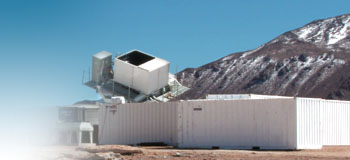
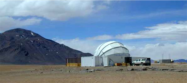
The pointing model for the CBI is determined from observations of stars using a 15 cm refractor and CCD camera mounted near the edge of the antenna platform. Typical pointing accuracy is better than 10''. The azimuth range of the CBI is -180o < az < 270o, with maximum slew speed of ~ 6o/s. The CBI is housed in a retractable dome which protects the instrument and workers from the weather. The dome is a 12-m diameter hemispherical steel space frame covered with polyethylene cloth shown in Figure 14a and Figure 14b.
|
| |
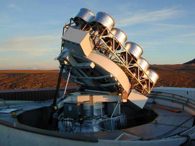
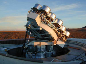 Figure 14a: Rear view of the CBI mount shows the elevation drive screw and the platform tipped up to an elevation of 45o; the dome is open. The existing antennas will be removed from the platform and replaced with the new 1-m and 2-m telescopes.
|
| |
 Figure 14b: View of the closed CBI dome with support facilities in shipping containers.
|
| |
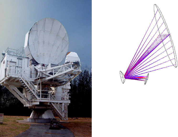
7m Optics In order to obtain a beam size small enough to gain sensitivity to B-mode fluctuations due to gravitational lensing, we require a primary mirror with a diameter around 6 m. The cost of developing a new telescope for this purpose would be substantial. We propose to move the existing Lucent Technologies 7m (Figure 15 left) to the CBI site in Chile. The optical properties of the 7m have been shown to be nearly ideal for CMB polarization measurements through our analysis and our prior experience with the CAPMAP experiment. In order to utilize the same feed horn focal plane as the 2-m systems, some modification of the 7m optics is required. The simplest solution allowing a 397 element 90 GHz array involves the manufacture of a new secondary mirror. Using the same design and analysis techniques described above, we have developed a design capable of meeting the QUIET requirements for the lensing observations. Although a full 4π sr plot of the beams from the 7m with modified optics was too computationally intensive for this proposal effort, we show a ray-trace optical design with a new secondary in Figure 15. Because control of spill-over is far more difficult on the 7m than the 2m, we chose to greatly underilluminate (as in CAPMAP) all of the optical elements on the redesigned 7m. As for the 2m, the performance of the central beam and an extreme beam are shown in Figure 16. While there is a loss of gain in the extreme beam position, the cross-polar response is excellent and the beam is still small enough to return all of our science objectives for the small scale observations.
|
| |
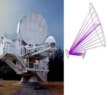 Figure 15: Left: Photograph of the 7m telescope in Holmdel, NJ. Right: Optical layout for the 7m with the new secondary mirror. The rays are traced for several of the 397 elements in the focal plane.
|
| |
 Figure 16: Fine Scale Optics co- and cross- polarization. Physical optics simulation of the beam response for a) copola central feed; b) cross-polar central feed; c) co-polar for x = 15'', y = 0'' edge feed position and; d) cross-polar for x = 15'', y = 0'' feed position. Co-polar contours are -3, -10, -20, -30, and -40 dB. Cross-polar contours are -40, -50, and -60 dBi. While the beam size is degrading at the edge of the array, the crucial cross-polar properties remain well behaved and sufficient for QUIET science.
|
| |
Ground Screens Given the unprecedented sensitivity of QUIET, it is imperative that we pay close attention to systematic effects. One of the greatest concerns is pick-up of polarized emission from the ground, the Sun, the Moon as well as other large foreground contaminants. Given the optical design, we can estimate the magnitude of the problem each of these foregrounds presents, and we can then fashion an approach towards managing the effects on the data.
For pickup from the ground, we base our estimate upon 4π sr PO calculations of the beam patterns. We have explored these far side-lobe patterns in detail for the initial one and two meter telescopes. The first line of defense against polarized ground pickup is a co-moving ground screen. This screen is small enough to fit on the platform, and is placed to throw the larger lobes, from primary and secondary spill-over towards the sky. Without a detailed geometry for the ground screen (which we will first estimate from ray tracing), PO calculations are impractical so we model it as a 20 dB attenuation of the side-lobes from the PO calculation below the local horizon. We then convolve this beam pattern as well as the original, with a model sky and horizon to estimate the effectiveness of the ground screen. We find that the co-moving ground screen is highly effective, reducing the horizon effect in the scan by more than 20 dB, to the level of about 10 µK.
Effects of any temperature variation across the horizon, while reduced by the ground screen, are not eliminated. These become a primary source of scan-synchronous offsets in the measurement. They can be controlled in at least two different ways; through the choice of scan strategy and analysis; and the use of a large fixed ground screen. Our experience on CAPMAP, using the 7m telescope, has demonstrated that scan-synchronous offsets, from structures on the horizon, occur at or below the 50 µK level. The effect of these offsets in the final data are reduced in analysis to of order a few µK. While the horizon at Atacama is far cleaner than the tree-lined site in NJ, we require exquisite precision to measure B-mode fluctuations. We similarly expect that in QUIET such residual offsets will be at the level of a few 100 nK.
We will also need a fixed ground screen. It must be large enough to shadow the horizon from the optics and at the same time withstand winds in excess of 100 knots at the CBI site, and must itself be stable thermally. We have included in our cost the fabrication of two fixed ground shields large enough to completely shield the CBI platform and the 7m telescope respectively. We do not intend to deploy these shields initially. We will use our Phase I observations with the smaller arrays to inform our decision-making as to the best design of a solid surrounding shield. Our beam analysis clearly shows that the dominant lobe structures are restricted in solid angle. We therefore believe that we can make use of judicious shielding in critical areas, given our limited azimuthal scan strategy. The first year of observations will provide the necessary data to inform this decision.
The ground screens we have costed will be manufactured from steel or aluminum frame members, with aluminum skins attached with fasteners. While the layout of the screen is ideally an inverted cone, it will have an octagonal cross-section for manufacturability.
|
| |
|
|